
ESP32 Mini Quadcopter Development Guide
A detailed getting-started guide for developing an ESP32-based UAV—from environment setup and hardware walkthrough to PID tuning.
Preface#
Do you remember looking up at the blue sky as a kid—watching airplanes draw white lines across it—and imagining the broad, open view an Air Force pilot sees when looking down at the earth? That kind of scene always sparked a desire to fly. Unfortunately, I never had the body to become a pilot, which is a bit of a regret. Luckily, with today’s technology and the boom of open-source hardware, I don’t have to be an aerospace engineer to build my own aircraft by hand—and to catch a glimpse of the scenes I once dreamed about.
This post will walk you through the process of building a small ESP32 quadcopter UAV. It won’t be a perfect product like a DJI drone. But every line of code and every solder joint here is a step toward the sky. Even if the most you’ve done before is light up an LED, as long as you follow this tutorial, you’ll be able to make these PCBs and motors fly.
I don’t want this to be a dry technical manual. I’d rather it be a flight diary that accompanies you as you explore the unknown. Ready? Let’s go for it!
Software Installation#
Before we can really fly, we need to set up the build environment first. Here we choose Espressif’s official ESP-IDF. The learning curve is a bit steeper, but it lets us control the hardware more deeply and makes it easier to diagnose issues later.
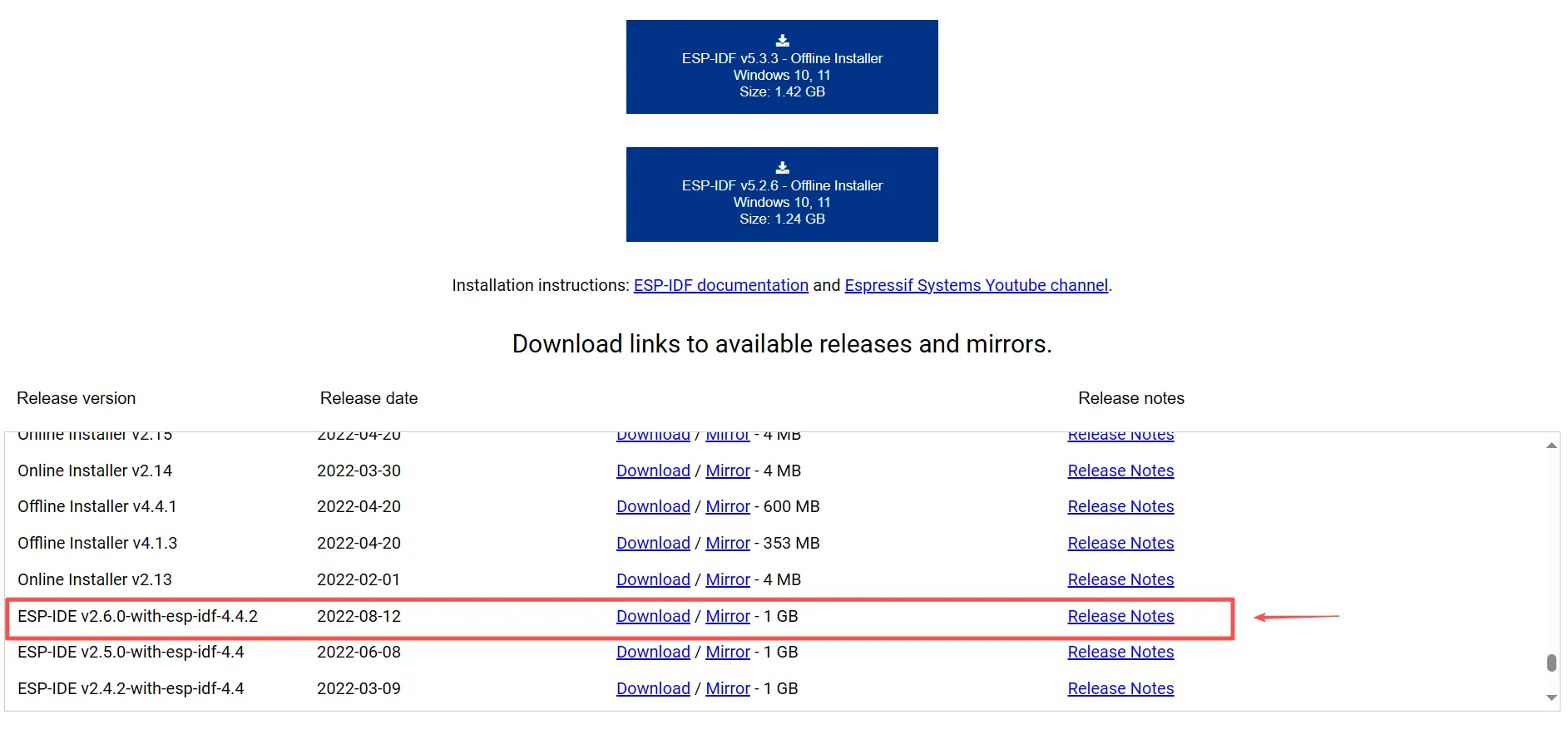
- Download the installer
First, we need the ESP-IDF Tools Installer. Go to Espressif’s download page ↗, scroll to the bottom, and find the version shown in the screenshot under previous releases (it’s best to install this specific version; other versions may come with various annoying issues). Then click Download. After it finishes, double-click to open it and start installation.
- Environment setup wizard
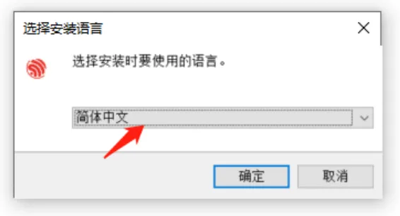
The installation is not complicated—just follow the wizard step by step:
- Choose language: the first thing after the installer starts is selecting a language. Pick whichever you prefer.
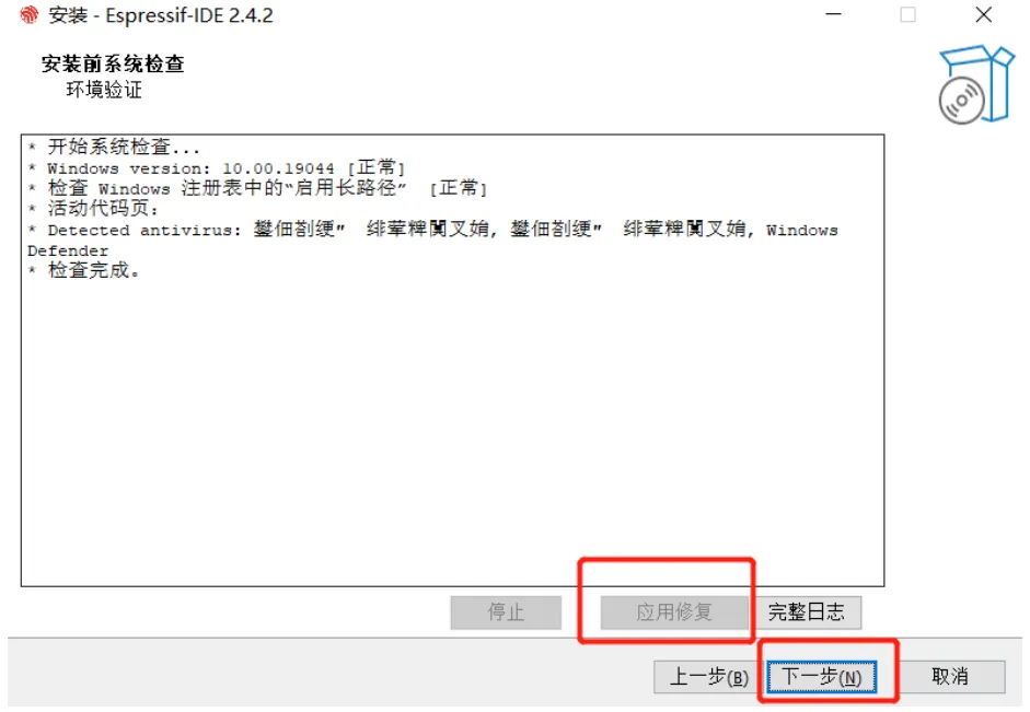
- Environment check: the program will automatically check your current system environment. If something is missing (like Python or Git), it will prompt you to install it.
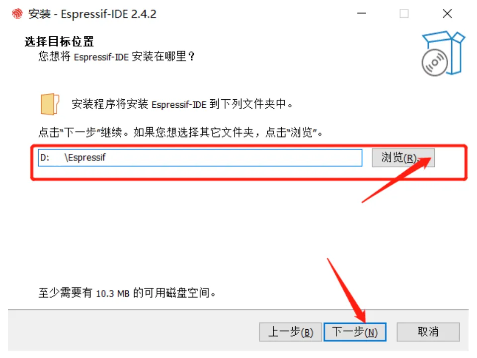
- Path settings: if this is your first installation, choose a suitable path on the following pages. But do not include Chinese characters or spaces—use an all-English path as much as possible, otherwise compilation errors later may make you question life.
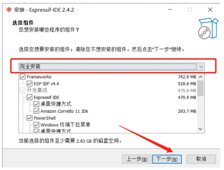
- Select components: here we choose the full installation. This is currently the more stable and feature-complete option. Just click next—avoid changing things unless you really need to.
- Wait for installation and fix drivers
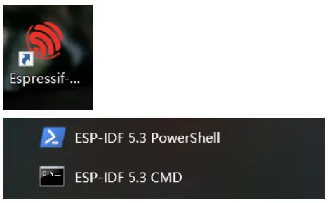
After clicking “Install,” the installer will automatically download and configure the required toolchain. When you see the “Installation complete” screen, the development environment is ready! At this point, you should see two black icons on your desktop: ESP-IDF 5.3 PowerShell and ESP-IDF 5.3 CMD. They are command-line development tools. There’s also a GUI tool Espressif IDF, which may be more beginner-friendly and more convenient.
Create a Project#
Now that the environment is ready, we should run something. In the embedded world, blinking an LED is a ritual, and printing “Hello World” is faith. Let’s have the ESP32 say hello to the world first.
- Launch and initialize
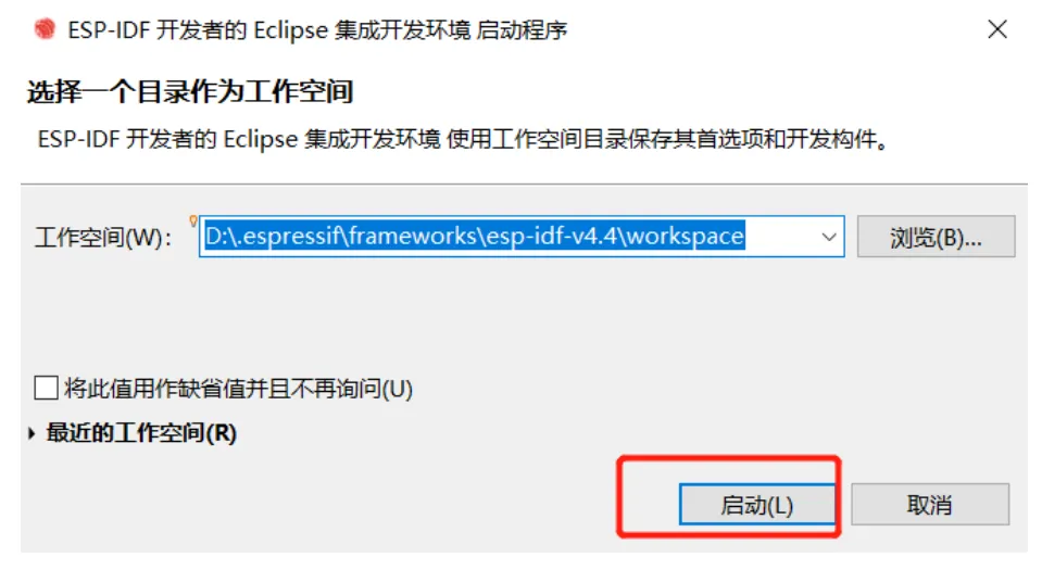
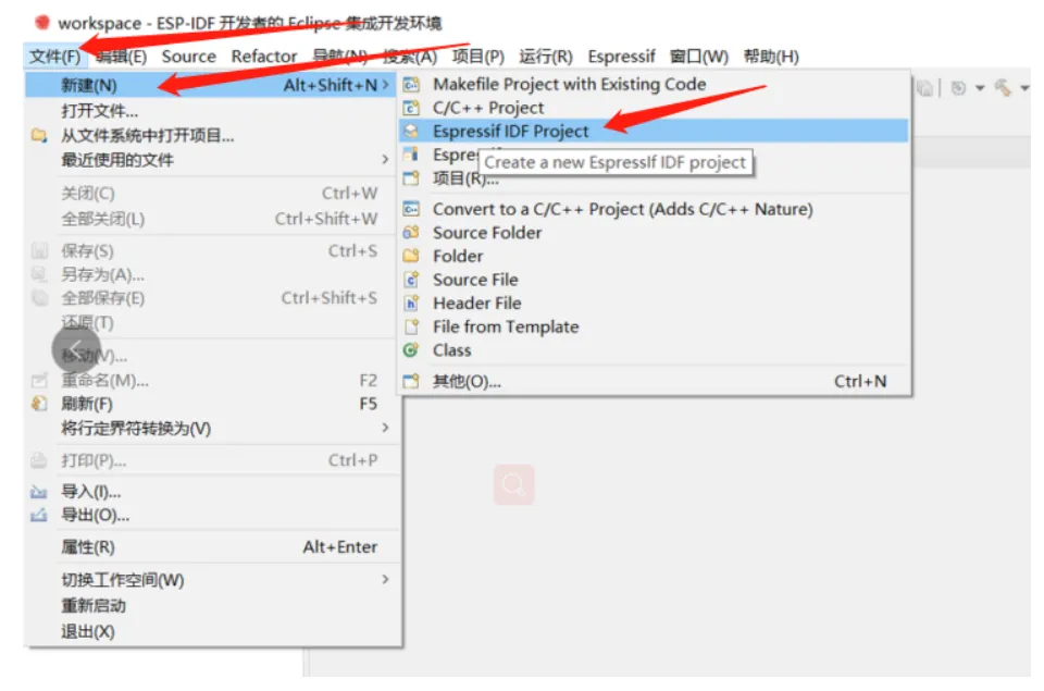
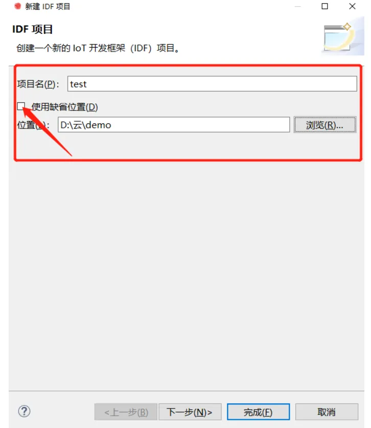
Double-click the Espressif IDF icon on your desktop. Start the software and create a workspace. Then create an IDF project inside it. Enter a project name, create a folder to store the project, and click “Next”.
- Build and flash
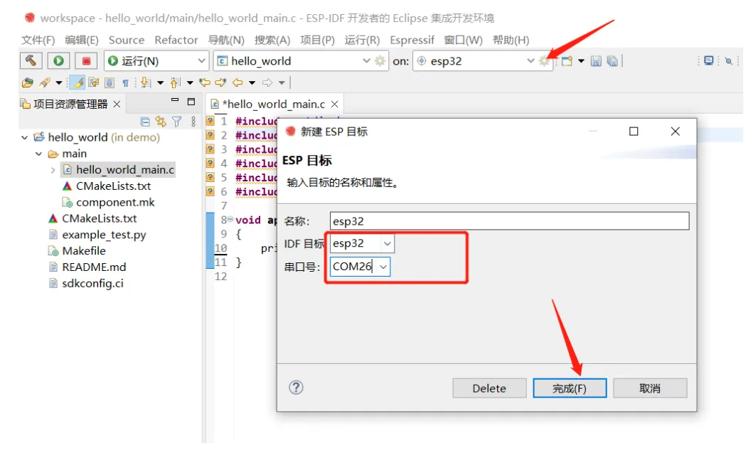
- Next, build, flash, and run monitoring. Remember to connect your development board, select the target chip model, and choose the serial port.
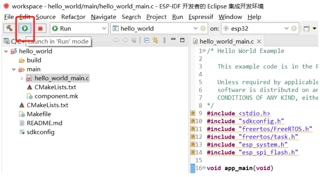
- Build / flash / monitor correspond to the three tools highlighted in the red box below.
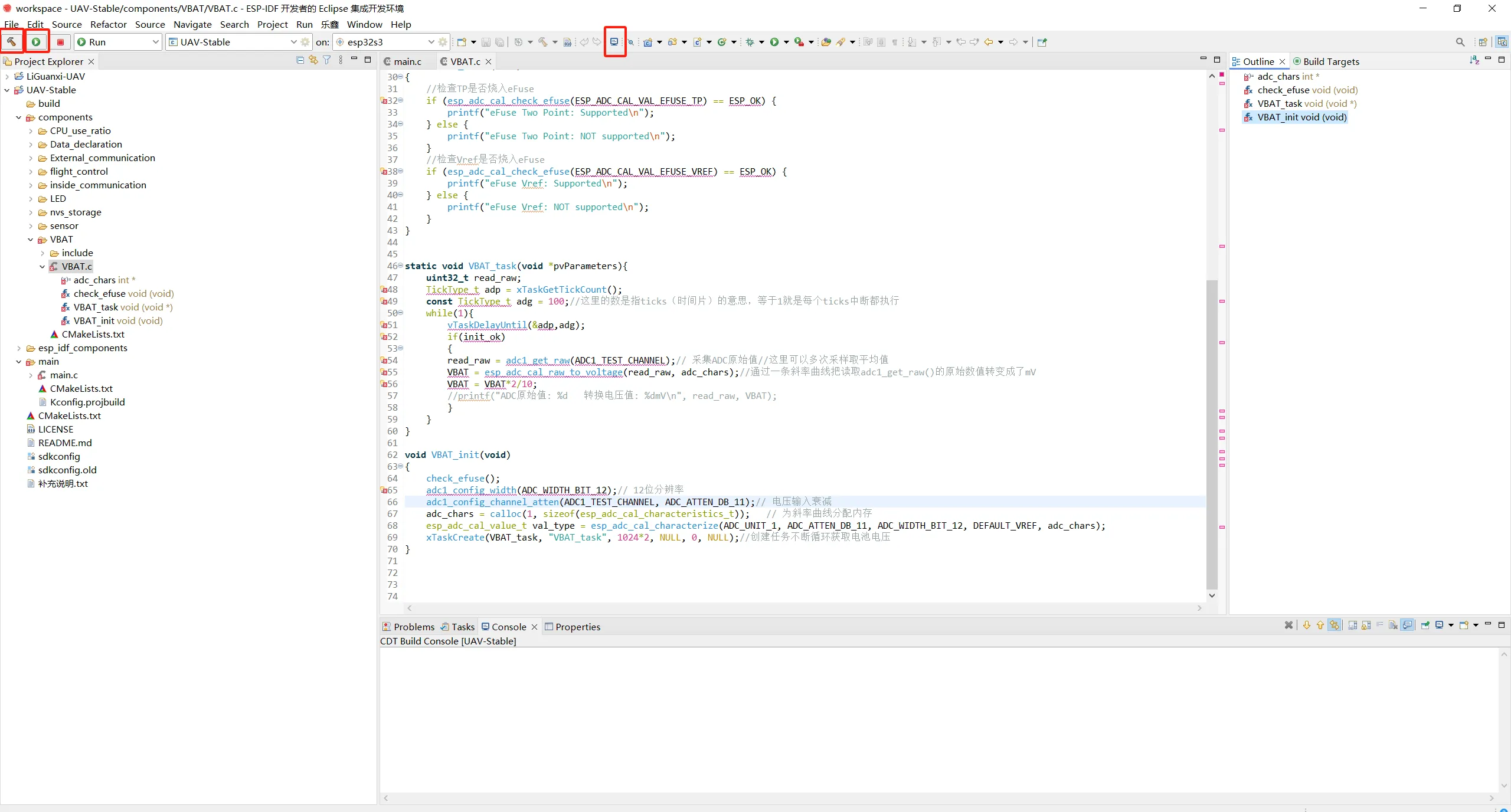
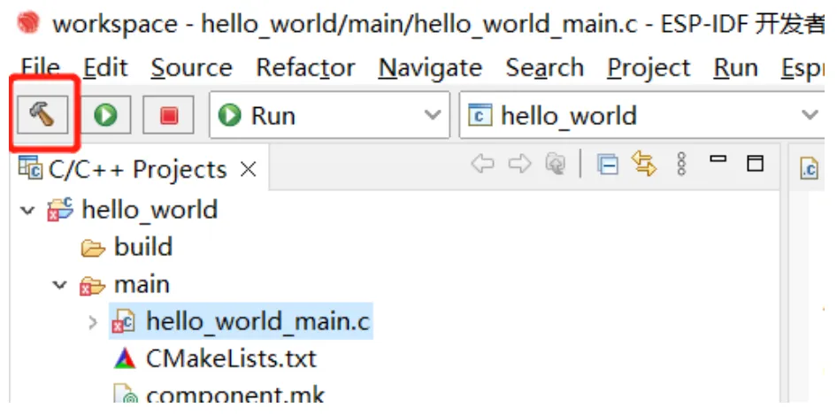
- Click the small hammer icon in the top-left of the toolbar to build the project.
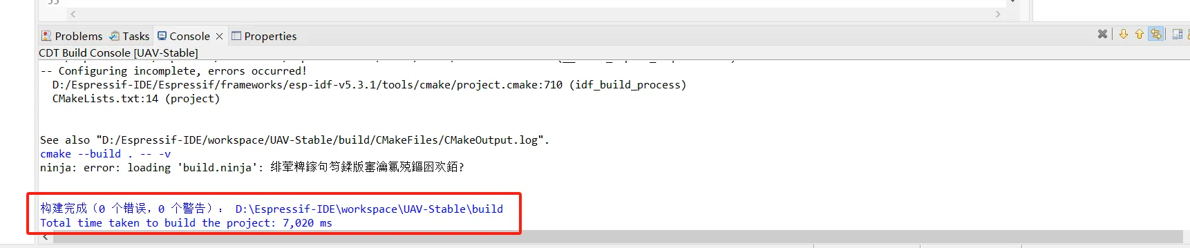
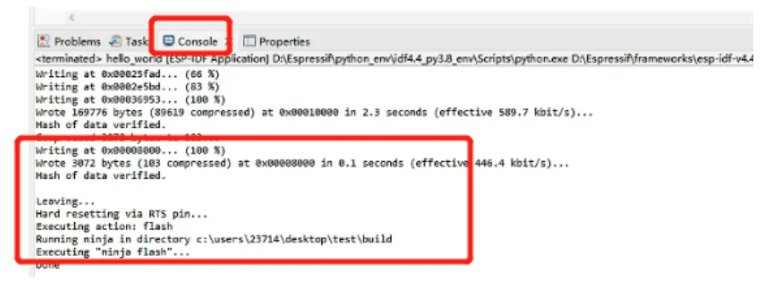
- When you see output like below in the “Console” panel, the build is done and you can flash.
- Click the triangle icon in the top-left to flash.
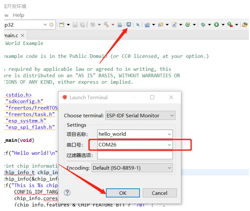
- Next, open the monitor to check the runtime output. Click the “small TV” icon in the top menu bar; you’ll see the dialog below. Usually the default options are fine—just click “OK”.
Hardware Walkthrough#
Now that the software environment is set up, let’s look at the hardware side. I won’t go into great detail about SMD soldering here; just prepare the parts according to the BOM and PCB files in my open-source repository ↗. Below are some small but important pieces of knowledge you’ll still need once everything is ready.
Hardware design plan#
-
Power: first use the ps7516 chip to boost battery voltage (3.7V-4.2V) up to 5V, then use AMS1117-3.3 to step it down to 3.3V. This mainly provides buffering.
-
Motors: use 8520 coreless motors. The shaft diameter is either 1.0 mm or 1.2 mm, and it must match the inner diameter of the propeller, otherwise it won’t fit. Even if you force it on, the propeller will be off-center.
-
Battery: use a 1S LiPo (length < 65, width < 17.5, thickness < 7.5). Common voltages are 3.7V and 3.8V. Choose 3.7V; both can work, but 3.8V is more likely to puff. Choose a PH2.0 connector for easier plugging/unplugging.
-
LED indicators
- Blue: aircraft status indicator, used to show which part of the internal flight-control loop is currently running, e.g. initializing or initialized but not armed.
- Battery indicator (Yellow): shows whether battery voltage is sufficient.
- Connection indicator (Green): shows the connection status between the flight controller and the ground station / remote controller.
- Power indicator (Red): lights up when powered on to indicate power is OK.
Enter download mode#
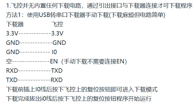
Our little aircraft uses the ESP32-S3-WROOM-1 (D2N8) module. It’s not just a Wi-Fi chip—its dual-core 240MHz compute power is enough to handle attitude estimation and PID control at the same time. For triggering the chip’s flashing mode, the circuit is set up like this. The download circuit is manual: press the boot and rst buttons on the flight controller to enter download mode (hold boot, then press rst once to enter download mode). Then you can flash via UART directly (buy a USB-to-UART adapter and connect the four pins rx, tx, 3.3V, gnd).
Hardware assembly and wiring#
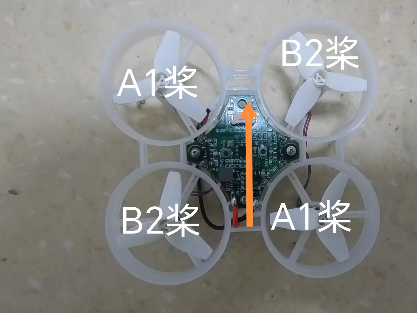
Motor ports: the four motor ports M1, M2, M3, M4 correspond to the four propellers.
Prop installation and motor wiring: be sure to install clockwise/counter-clockwise props correctly! Usually diagonal motors rotate in the same direction (e.g., M1/M3 clockwise, M2/M4 counter-clockwise), and props must match (A props for clockwise motors, B props for counter-clockwise motors). If you install them wrong, the aircraft will spin in place or crash immediately. Also, we use red/blue wire motors because many black-wire motors sold today rotate opposite to the program’s definition. If you want to use black/white wire motors, you need to manually swap the wire order.
Software Architecture#
- Attitude estimation (AHRS)
To fly stably, the aircraft must first know whether it is “tilted.” We use the MPU6050 6-axis sensor (3-axis accelerometer + 3-axis gyroscope).
- Read data: via the I2C bus, we continuously read raw MPU6050 data.
- Complementary filter / Kalman filter: raw data is noisy. The accelerometer is unreliable during aggressive motion, and the gyroscope has drift. We combine them to compute clean and accurate Euler angles (Pitch, Roll, Yaw).
- PID control
This is the core algorithmic design of the whole post. The PID (Proportional-Integral-Derivative) controller is one of the most important parts for resisting gravity and disturbances.
-
Outer loop (angle loop):
- Target is the desired angle from the remote controller (e.g., I want the aircraft to pitch forward by 10 degrees).
- Input is the current angle; output is the desired angular rate.
- In short: I want the aircraft to tilt a bit, and PID computes how fast it should rotate.
-
Inner loop (angular-rate loop):
- Target is the desired angular rate from the outer loop.
- Input is the measured angular rate from the gyroscope; output is the PWM throttle value sent directly to the motors.
- In short: to reach that rotation speed, how much power should I give the motors?
- Motor mixing
After we compute the control outputs needed for Pitch, Roll, and Yaw, how do we distribute them to the four motors? That requires a mixing algorithm.
motor1 = throttle + pitch_out + roll_out - yaw_out;
motor2 = throttle + pitch_out - roll_out + yaw_out;
motor3 = throttle - pitch_out - roll_out - yaw_out;
motor4 = throttle - pitch_out + roll_out + yaw_out;(Note: the exact +/- signs depend on your motor layout and rotation definition; this is only an illustration.)
Ground Station Debugging#
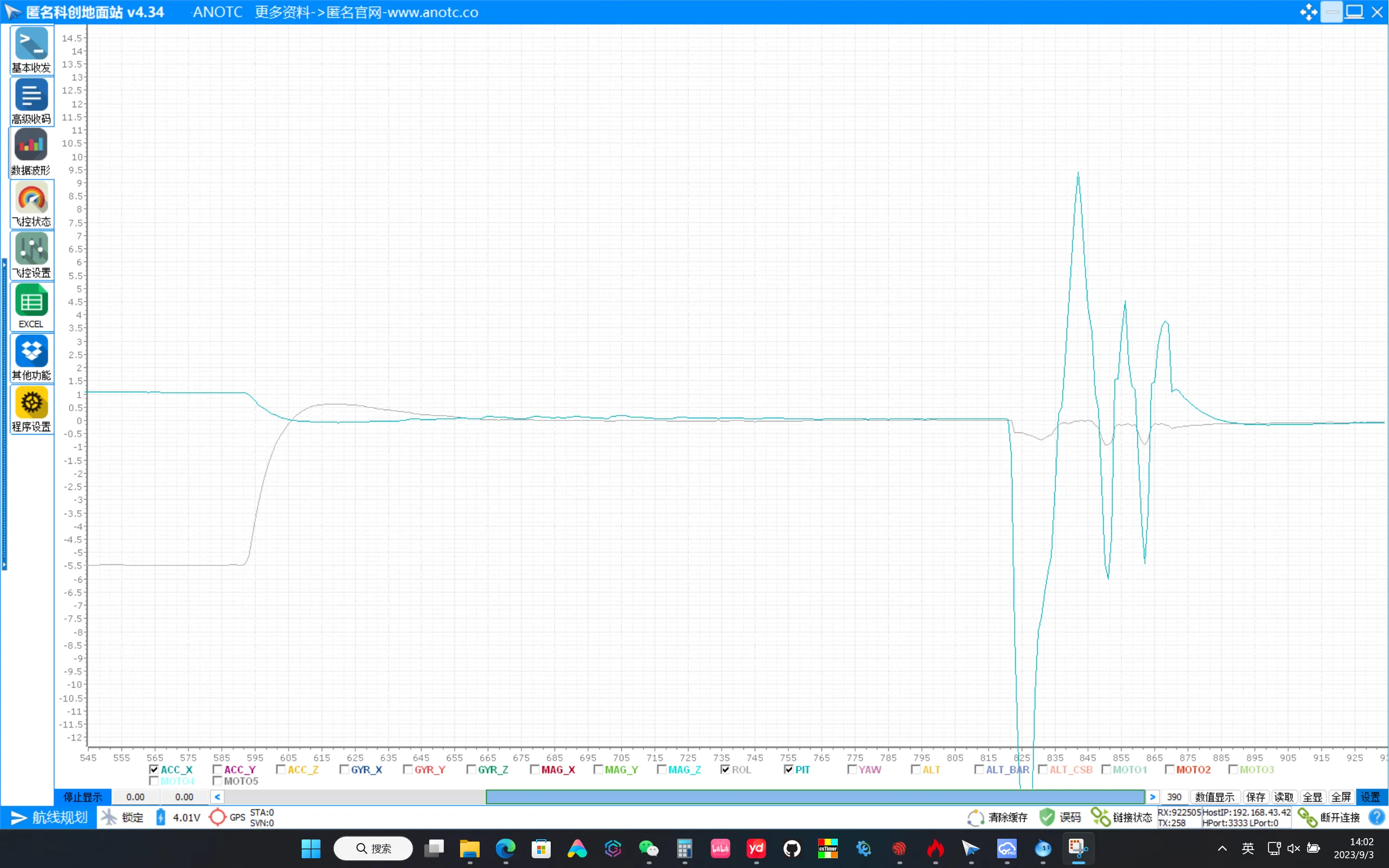
During flight, it’s hard to judge whether PID parameters are good or bad with the naked eye. That’s when a ground control station (GCS) helps. I recommend AnoTC (Anonymous Ground Station).
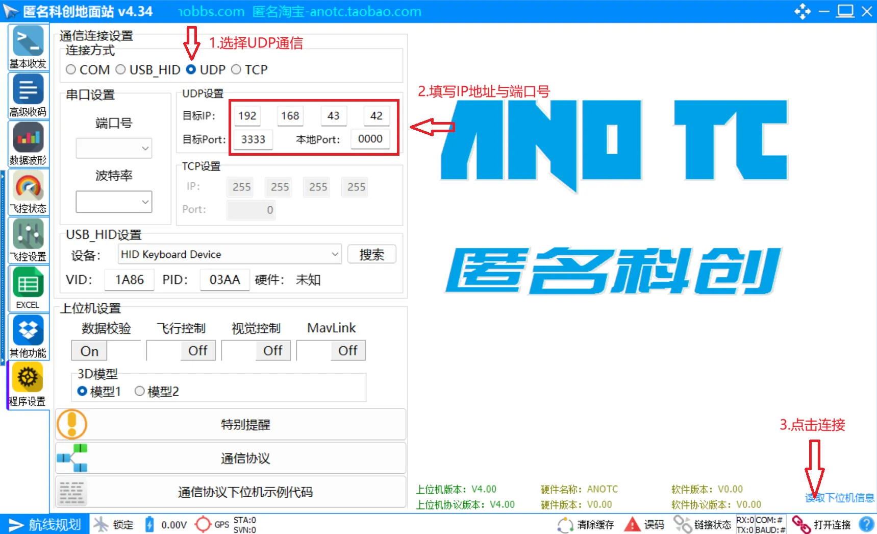
- Connect: connect the ESP32 via USB or Wi-Fi telemetry.
- Waveform observation: in the GCS, you can view real-time attitude curves.
- Online parameter tuning: no need to re-flash every time you change parameters. Via the protocol, you can modify PID parameters in real time and see the effect immediately.
Conclusion#
From a single build-and-flash command to the moment the aircraft trembles into the air for the first time, you may go through countless crashes, broken props, and compile errors. But when the algorithm you wrote by hand makes the aircraft hover steadily in the air, the sense of achievement is unmatched.
This post mainly helps you sort out the overall workflow of ESP32 UAV development. Later I’ll add more practical photos and detailed wiring diagrams in the corresponding places.